
 Your location:
1、 Composition of the laboratory ventilation system.
1. Indoor equipment requiring ventilation:
Such as: fume hood, atomic absorption hood, universal exhaust hood, storage cabinet requiring exhaust, etc. The exhaust equipment is generally equipped with electric or manual valves.
2. Ventilation duct:
Such as round pipe (PVC, PP, GRP), square pipe (PVC, PP, GRP), elbow tee, etc
3. Valve
Such as: manual/electric diverter valve, check valve, manual/electric fire damper, soft joint.
4. Make up/exhaust fan:
For example: square/round axial flow fan, diagonal flow fan, centrifugal fan.
5. Control system
For example: switch control, general starting control, variable frequency starting control system, static pressure variable frequency energy-saving system, one-stop intelligent control system, computer central control system, remote assistance control system.
6. Purification equipment
Such as: direct discharge spray purification tower, dosing circulating spray tower, activated carbon adsorption tank.
7. Power cable.
Such as YJV interactive cable and VV power cable.
2、 Noun resolution:
1. Fume hood:
The fume hood is a commonly used ventilation equipment in the laboratory, which is mainly used in experiments that produce odor, smoke, toxic and harmful gases, such as digestion, decomposition, dry steaming, emulsification, atomization, high temperature melting, high temperature carbonization, etc. It is equipped with lighting, sockets, water supply and air supply, a door that pushes up and down, and a translation window on some doors. There is an air valve on the top of the cabinet to control the air displacement. The air valve is electric/manual. The electric valve is an ordinary on-off valve and an integral proportional valve. The ordinary on-off valve locates the opening of the air valve through the control switch, and discharges air in a fixed amount. The integral proportional valve is set by the face wind speed of the VAV controller. When the opening of the door of the fume hood changes, the opening of the air valve is automatically adjusted, Maintain a constant surface wind speed and exhaust air with variable air volume, which plays an energy saving role. In practical projects, the air valve is usually connected to the main or branch exhaust pipe through a hose or a round pipe. In practical projects, several fume hoods are usually connected to an exhaust fan.
According to the size of the cabinet door, there are generally three types of fume hoods: 1200 type, 1500 type, 1800 type. According to the appearance, there are also three types: floor type, central cabinet type, desktop type. The general algorithm for maximum exhaust air volume. Desktop type: 1200 type 1200m3/h, 1500 type 1500m3/h, 1800 type 1800m3/h, central cabinet type: 1200 type 1500m3/h, 1500 type 2000m3/h, 1800 type 2300m3/h, floor type: 1200 type 1500m3/h, 1500 type 2000m3/h 2300m3/h for 1800 type. In the actual project, during the acceptance (VAV fume hood is not included), when the opening height of the fume hood door is 300mm and the surface wind speed reaches 0.3~0.7m/s, it is deemed as qualified, and when it is stabilized at 0.5m/s, it is considered as up to the international standard.
2. Atomic absorption hood:
The atomic absorption hood is generally made of stainless steel according to the actual needs of customers. It usually has a manual air valve, which is usually used on fixed equipment or instruments. Its maximum exhaust air volume is calculated according to the size of the hood exhaust outlet. For 160 tubes, it is 300 m3/h, for 200 tubes, it is 500 m3/h, for 250 tubes, it is 700 m3/h, and for 315 tubes, it is 1200 m3/h. In the actual project, the air velocity at the hood exhaust outlet shall be more than 3m/s during acceptance.
3. Universal exhaust hood:
It is a molded product with professional manufacturers, capable of universal movement. It is usually used in micro experiments, and the maximum exhaust air volume is generally calculated as 300m3/h. In the actual project, the air velocity at the hood exhaust outlet shall be more than 4m/s during acceptance.
4. Storage cabinets requiring ventilation:
Generally, storage cabinets with volatile drugs or reagents are equipped with ventilation function. The maximum exhaust air volume is calculated according to the size of the exhaust outlet. For 160 pipes, it is 300m3/h, for 200 pipes, it is 500m3/h, for 250 pipes, it is 700m3/h, and for 315 pipes, it is 1200m3/h. In the actual project, the wind speed at the exhaust outlet shall be more than 2m/s during acceptance.
5. Manual/electric diverter valve:
Made of all steel, most of them are multi leaf valves. It is mainly used to balance the exhaust air volume when a make-up/exhaust fan has two or more branch pipes.
6. Check valve:
It is made of all steel, also called one-way valve, and most of them are multi leaf valves. It is mainly used to prevent backflow when there is dual power air source.
7. Manual/electric fire damper:
Molding products, there are professional manufacturers. It is installed at the place where the branch pipe or main pipe enters the wall to prevent the spread of fire.
8. Flexible joint:
There are canvas and silicone materials. It is mainly used for power source and pipe interface, such as fan and main pipe connection.
9. Square/round axial flow fan:
The fan installed on the pipe for direct exhaust/air supply is made of all steel and fiberglass. The exhaust air volume and other parameters are indicated on the nameplate of the fan.
10. Diagonal flow fan:
Axial flow fan with pressurization function is generally made of glass fiber reinforced plastic. The exhaust air volume and other parameters are indicated on the nameplate of the fan.
11. Centrifugal fan:
There are box type and seat type, which are made of all steel and glass fiber reinforced plastic. The box type centrifugal fan is generally used indoors, while the seat type centrifugal fan is mostly used outdoors. The exhaust volume and other parameters are indicated on the nameplate of the fan.
12. Switch control (direct start):
The motor is controlled by switch. Generally, the air switch (miniature circuit breaker) is used. Most of them are used for small power motor control, and the fan is directly powered to start.
13. Common startup control (power frequency startup):
The motor adopts common control circuit, and the starting circuit controls the contactor to start the fan indirectly.
14. Variable frequency starting control system:
The fan can be started linearly through the variable frequency speed regulation controller to protect the motor and reduce noise. At the same time, the fan can be controlled at a constant speed as required, saving redundancy and saving energy. (The system will provide detailed scheme description separately)
15. Static pressure frequency conversion energy-saving system:
The frequency conversion control system of PID closed-loop control is added, and the fan speed can be automatically adjusted according to the actual load (exhaust air volume) to achieve the purpose of energy saving. (The system will provide detailed scheme description separately)
16. Room negative pressure control system:
According to the negative pressure value set in the room, control the air make-up fan or air valve, make up the air volume and exhaust the air volume to achieve a relative balance, maintain the negative pressure of the room, prevent the laboratory air from leaking to the office area, and achieve the green environmental protection function. (The system will provide detailed scheme description separately)
17. One stop intelligent control system:
When there are multiple exhaust fans and forced draft fans in the laboratory, one-stop control can be realized at suitable locations on the site, replacing the multi-point control mode of one fan corresponding to one control point, saving space and material costs, and convenient operation. (The system will provide detailed scheme description separately)
18. Computer central monitoring system:
Through the bus or Ethernet communication, the computer communicates information and data with each control station, and realizes the central monitoring of the entire laboratory on the office computer. The upper supervisor can know the status of the experimental equipment in real time, which is convenient for management. (The system will provide detailed scheme description separately)
19. Remote Assistance Control System:
Through Ethernet, the laboratory can be monitored in different places. (The system will provide detailed scheme description separately)
20. Direct discharge spray purification tower:
The soluble odorous gas that is not toxic and harmful is directly discharged without treatment after spraying and filtering. The spray tower is composed of tower body, water pump and water system. The exhaust air volume and other parameters are indicated on the nameplate.
21. Dosing type circulating spray tower:
Toxic, harmful, strong acid-base soluble gas, after spraying and filtering, the sprayed water is collected in the water tank of the spray tower, treated with chemicals, and used for circulating spraying. The spray tower is composed of tower body, water tank, water pump, water system and dosing system. The exhaust air volume and other parameters are indicated on the nameplate.
22. Activated carbon adsorption tank:
Insoluble in water, toxic, harmful or odorous gases can be absorbed and filtered by activated carbon to reduce toxicity or odor. The activated carbon adsorption box is generally square, and the exhaust air volume and other parameters are indicated on the nameplate.
23. YJV interactive cable and VV power cable:
YJV interactive cable is generally used when the line distance is long (more than 30 meters) to reduce voltage drop.
VV power cable, common cable.
When the cable is used, the theoretical bearing capacity of each mm2 copper wire section is calculated according to 4A current. In actual use, it is configured to ± 2A according to the rated current marked on the motor nameplate.
Chapter 2: Variable Frequency Start Control System
1. The inverter is used to control the start/stop of the fan. The inverter is installed in the control cabinet equipped with the basic starting circuit. On the panel of the control cabinet, the start and stop buttons are installed. In the actual project, the system has been installed and debugged. The field staff can keep the ventilation system working normally by pressing the start and stop buttons.
2. The fan motor can be started linearly through the variable frequency speed control controller to protect the motor from noise. At the same time, the fan can be controlled at a constant speed by setting the parameters of the frequency converter as required to save redundancy and have a certain energy saving effect. Among them, redundancy refers to the design of matching fans in the ventilation system. The matching fans are generally larger, sometimes much larger, than the actual required exhaust volume, Especially when the customer's budget will expand the equipment in the future, the part with more design than application is called redundancy.
3. In actual engineering projects, if the equipment used by the customer is relatively fixed in daily work, all the equipment requiring air exhaust is usually kept in the normally open state. Considering the investment cost and energy conservation, we recommend customers to use this variable frequency starting control system to save the investment cost of supporting more advanced systems, save redundancy, achieve energy-saving functions and reduce operating costs.
4. Variable frequency starting control system, air make-up fan and exhaust fan are applicable. In the actual design process, we also need to consider supporting air make-up system to reflect our professional services. The air make-up and exhaust control systems are installed in the same control cabinet. Through the parameter setting of the frequency converter, the linkage of air exhaust and air make-up is achieved. The air make-up volume is based on the exhaust volume to achieve the air make-up according to the percentage relationship, maintain the air flow balance in the laboratory, and greatly reduce the energy loss (here refers to the energy consumption of the air conditioner).
5. System framework diagram
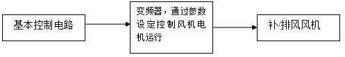 Ventilation system control scheme
 Chapter 3: Static Pressure Variable Frequency Energy Saving System
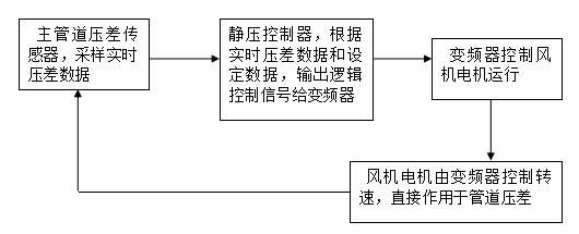
1. The closed loop control system is composed of pipeline negative pressure sensor, static pressure controller and frequency converter. The negative pressure sensor is installed on the exhaust duct system and the gentle section of the main pipe, sampling the negative pressure value of the main pipe, and inputting the real-time negative pressure value of the main pipe to the static pressure controller. The static pressure controller is installed on the panel of the frequency conversion control cabinet. Through the parameter setting of the static pressure controller, the control signal is output to the frequency converter, which controls the operation of the fan motor according to the signal of the static pressure controller. The inverter control cabinet is equipped with a starting circuit. On the panel of the control cabinet, start and stop buttons are installed. In the actual project, the system has been installed and debugged. The field staff can keep the ventilation system working normally by simply pressing the start and stop buttons. When the field supervisor needs to change the exhaust air volume, the purpose can be achieved by changing the parameters on the static pressure controller. For example, when the exhaust equipment needs to be increased, the set value of the static pressure controller increases.
2. The static pressure controller, installed on the panel of the frequency conversion control cabinet, has two windows, one displaying the set value and the other displaying the actual value. The displayed data is the negative pressure value of the main pipe. When the exhaust equipment is fixed (when the exhaust air volume is fixed), the negative pressure value is proportional to the system exhaust air volume. The greater the set value, the greater the system exhaust air volume.
3. In the actual laboratory application, the main function of the static pressure frequency conversion control system is to save energy and reduce emissions. After the setting of the static pressure controller parameters, the system automatically adjusts the rotation speed of the exhaust fan motor when the usage or status of the exhaust equipment changes (the exhaust air volume changes) in the application process, so as to keep the negative pressure of the pipeline relatively stable at the set value. When the usage of the exhaust equipment decreases, the fan motor speed slows down to reduce energy consumption, Achieve the effect of energy conservation and emission reduction.
For example: an exhaust system with five fume hoods, five fume hoods are in normal use (door opening is 500mm), the static pressure setting value is 250, and the displayed value is kept at about 250. The inverter operates at 45Hz, and the fan motor operates at high speed. When three of them are not in use or the door opening is close to closing, the displayed value is kept at about 250 after the automatic adjustment of the system is completed, the inverter operates at about 28Hz, and the fan motor operates at medium speed, Frequency is proportional to energy consumption. The lower the frequency, the less energy consumption.
4. In the actual engineering projects, the current engineering projects in the industry have basically adopted the static pressure frequency conversion control system (above 1KW fan). The main consideration is the theme of energy conservation, noise reduction and emission reduction, At the same time, it can reduce the noise and make the laboratory more comfortable.
5. Static pressure frequency conversion control system, air make-up fan and exhaust fan are applicable. In the actual design process, we also need to consider supporting air make-up system to reflect our professional services. The air make-up and exhaust control systems are installed in the same control cabinet. Through the parameter setting of the frequency converter, the linkage of air exhaust and air make-up is achieved. The air make-up volume is based on the exhaust volume to achieve the air make-up according to the percentage relationship, maintain the air flow balance in the laboratory, and greatly reduce the energy loss (here refers to the energy consumption of the air conditioner).
6. Air supplement is mainly used to maintain the balance of air pressure in the laboratory. Generally, in the application of purification laboratory, the room negative pressure system is used to control the air supplement volume instead of one to one ratio air supplement. The air supplement volume can be realized by directly controlling the air supplement fan and controlling the air supplement valve in the room. According to the negative pressure value set by the room negative pressure system, the air supplement volume can be automatically adjusted to maintain the balance of air pressure in the room.
7. System framework diagram
Chapter 4: Room Negative Pressure Control System
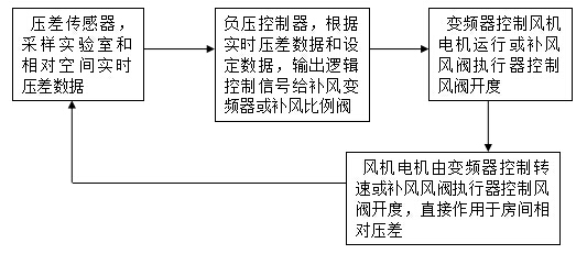
1. The closed loop control system is composed of a room differential pressure sensor, a room negative pressure controller, a frequency conversion controller for the air make-up fan (or a room air make-up proportional valve). The differential pressure sensor is installed between the room and the relative space (such as the laboratory and corridor). The relative differential pressure of the sampling room and the differential pressure data are input into the room negative pressure controller. Through the parameter setting of the room negative pressure controller (the room negative pressure value setting), the control signal is output to control the air make-up fan (or the room air make-up proportional valve), and the room differential pressure balance is automatically adjusted to prevent the laboratory gas from leaking into the relative space.
2. The room negative pressure controller is generally installed in the room. At present, most of them are DDC controllers with detailed menu settings. When the negative pressure value of the room is set, the negative pressure controller will automatically adjust the make-up air volume according to the actual situation to maintain the room in the set negative pressure state.
3. In actual engineering projects, the room negative pressure control system is generally applied in the clean room project, especially in laboratories with multiple clean rooms. In order to prevent gas mixing between rooms, the requirements for negative pressure are high (ordinary laboratories only prevent indoor gas leakage, maintain a certain negative pressure, and mostly adopt proportional air supplement).
4. In the actual project, the problem of air supplement must be considered in the marketing and design. If it is not suitable to install dynamic air supplement, it must be equipped with natural air supplement, which is mainly to open air supplement windows. If it is a clean laboratory, it must consider the use of room negative pressure control system.
5. System framework diagram
Chapter 5: One stop intelligent control system
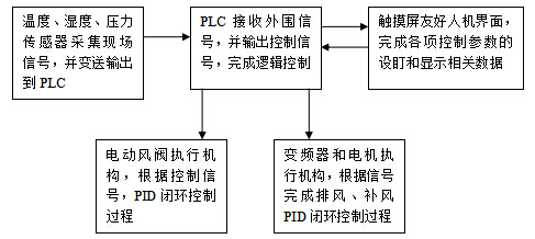
1. The PLC and touch screen are used to form a field control system. The temperature, humidity and pressure sensors sample the field information and input it to the PLC controller for data processing. The PLC outputs control signals to the frequency converter and air valve actuator for control according to the needs of control logic. The touch screen, as a human-computer interface, realizes control settings and data display, and can realize manual/automatic functions.
System framework
Ventilation system control scheme Ventilation system control scheme Ventilation system control scheme
2. The one-stop intelligent control system has not been in the laboratory for long. It has only appeared in some high-end laboratories in the past two years