YGM305
Explosion-Proof Air flow Transmitter
Product Maintenance Manual
Service Information:
Nanjing Engma Instrument Technology Co.,Ltd.
Address:
Floor 3,building 1,no.9 yongfeng avenue,qinhuai district,nanjing
Qinhuai District
Nanjing
Tel:(+86)18951760149
FAX:025-84809175
Table of Contents
2.4 Measuring film purging instructions
1. Abstract
1.1 General Notes
(1) In any case, non-standard operation may cause injury to personnel and equipment. Please comply with the safety regulations of all electrical appliances and equipment.
(2) Please confirm that the power supply has been disconnected before repairing and removing electrical components!
(3) Before switching on the power, please confirm that all external wiring is correct. Any short circuit may cause data loss or program damage of the display.
1.2 Safety regulations
In order to ensure electrical safety and explosion-proof requirements, the instrument housing must be connected with the protection ground wire of the instrument work site, the ground resistance shall not be greater than 4Ω (ohm), the instrument housing shall not be connected with the neutral line (N).
This product is explosion-proof, can be used for the continuous determination of flammable gas.
1.3 Introduction
YGM305 is an explosion-proof product specially designed for explosive dangerous places. It has passed the PLd safety certification and ATEX explosion-proof certification. The probe part of YGM305 adopts diamond-shaped uniform velocity measuring plate, which can measure the mean wind speed at multiple points.
1.4 Application
Environment temperature:-20~+60℃
Relative humidity:0 ~ 85%RH
1.5 Main technical indicators
Measurement range: Choose according to the field air flow (wind speed)
Precision: ±4%FS (stable air flow rate)
Current output type: 4~20mA (three-wire system), load resistance RL≤500Ω
Voltage output type: 0~10V (three-wire system), load resistance RL≥10KΩ
RS485 output: standard ModBus-RTU
Response time: T90 ≤ 3s
Power supply: 20 to 28VDC
Electrical connection: M16 x 1.5, cable diameter: 4~8mm
Enclosure protection class: IP65
Working pressure: less than 1Bar
Working temperature: transmitter: -20~40℃
Measuring film: -40~80℃, -40~200℃ (optional)
2. Installation
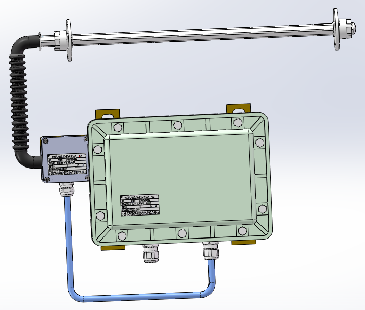
2.1 Installation dimensions
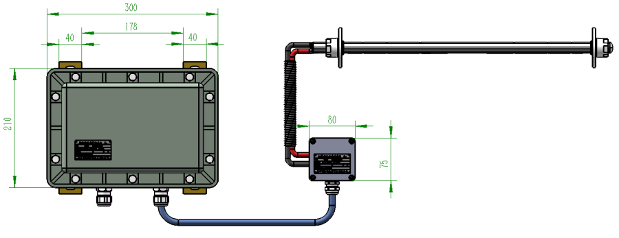

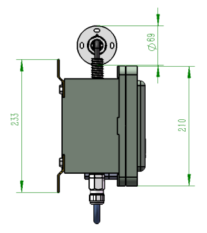
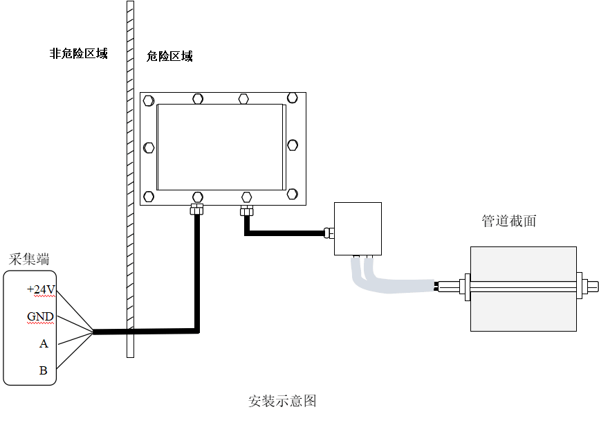
2.2 Installation diagram
2.3 Installation Instructions
(1) The measuring film should be installed in the straight section of the air duct. Because of the uneven wind speed at the bend of the air duct, the measurement accuracy will be greatly reduced.
(2) The distance between the windward side of the measuring film and the bend pipe should be more than 2~5 times the diameter of the wind pipe, and the distance between the leeward side and the bend pipe should be more than 2 times the diameter of the wind pipe. If the conditions cannot be met, ensure that the windward straight pipe section is longer than the leeward straight pipe section when selecting the installation position.
(3) The measuring film should be installed in the center of the air duct.
(4) When installing, a through hole should be made in the air duct. The two holes must be in a straight line to ensure that the Measuring film can pass through the two holes. The aperture is the maximum diameter of the test piece for drilling -- that is, the distance between the two diamond corners of the test piece.
(5) During installation, the midpoint of the first hole and the last hole of the measuring film is required to coincide with the center of the air duct. If the air duct is column type, it is installed on the diameter of the air duct. If the air duct is rectangular, the drilling position should be determined by the level or distance positioning method. The drilling position can also be determined by the distance between the air duct flange. For example, the distance between the two flanges of the air duct is 4m and the height is 2m. The center hole of the air duct is measured 2m from the flange and 1m from the top through a scale.
(6) Installation direction. The "+" mark is engraved on the probe position of the measuring film. During installation, install the "+" on the windward side. Install the flange first to determine the sensor installation direction. Flange installation requirements, rounded Angle horizontal to the wind direction, diamond Angle perpendicular to the wind direction.

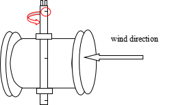 (7) Flange installation must be accurate. After the flange is determined, the sensor can be installed.
2.4 Measuring film purging instructions:
This product is mainly used for the measurement of the flow rate of clean gas, and can also be used for the measurement of a small amount of turbidity gas. For example, there is a small amount of liquid and steam, a small amount of sediment and adhesion in the pipeline. When it is used for the measurement of turbidity gas, the acquisition hole of the uniform velocity test piece may be clogged, so it is necessary to regularly purge the test piece.
(1)Disconnect the equivelocity gauge from the end of the connection between the sensor and the pressure primer.
As shown in figure 1;
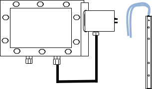
Figure 1
(2) Connect the pressure lead pipes at the two outlets to the air compressor for purging and discharge the accumulated pollutants in the Measuring film, as shown in Figure 2; In the absence of an air compressor, pollutants can also be discharged by blowing air directly through the mouth, as shown in Figure 3.
(4)Tighten the screws on the top of the cleaned measuring film, connect the pressure lead pipe to the positive and negative pressure lead ports of the sensor, and complete the uniform test piece purge process.
3. Instrumentation
3.1Wiring
(1)Wiring in sensor box

+24V
PGND
OUT
GND
(2)Wiring in transmitter box

24V+
PGND
A (RS485-A)
B (RS485-B)
3.2Data reading
(1) Communication interface
Standard: RS485
Working mode: serial, asynchronous, half duplex
Data format: start bit 1, data bit 8, stop bit 1, no parity check
Communication rate: 9600 bit/s
The address polling interval is at least 30ms
(2) Means of communication
Communication protocol: ModBus-RTU
Command code: 030
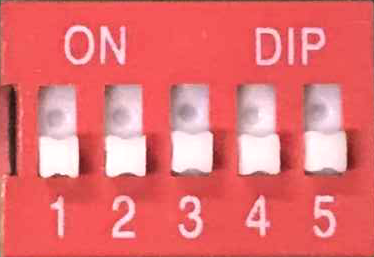
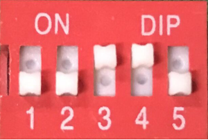 Communication address: 5-bit dip switch for setting (please complete the setting before starting up)
The DIP switch has five digits: 1, 2, 3, 4, and 5. Each digit represents a value. When the switch is dialed to the ON position, it is 0, and the position dialed to ON is 1. When the digits 1, 2, 3, 4 and 5 are dialed to the ON position, the value of the digit is 1, 2, 4, 8 and 16 in turn. Adding the values represented by each digit dialed to the ON position is the address code of the machine. As shown in Figure 1, the address is 0+0+0+0 +0=0. In Figure 2, the address is 0+0+4+8+0=12, and the maximum address code is 31.
Register address: 0X0000
Wind speed packet format: The output of two hexadecimal numbers represents the high and low value of the hexadecimal number after the wind speed is expanded by 10 times.
If the received data is 01 03 02 00 69 78 6A, 00 69 is the read data.
The corresponding calculation method of wind speed is: wind speed =0x0069/10=10.5m/s.
Air volume packet format: four hexadecimal numbers output the high value and low value of the hexadecimal number representing the air volume.
If the received data is 01 03 04 00 04 65 00 90 A2, 00 04 65 00 is the read data.
The corresponding air volume calculation method is as follows: Air volume =0x00 04 65 00=288000m3/h.
Data reading:
|
Address |
Command |
Register address |
Length |
CRC(low) |
CRC(high) |
|
1Byte |
1Byte |
2Byte |
N*2Byte |
1Byte |
1Byte |
Feedback:
|
Address |
Command |
Length |
Data |
CRC(low) |
CRC(high) |
|
1Byte |
1Byte |
2N*1Byte |
2N*1Byte |
1Byte |
1Byte |
Example
Send:01 03 00 00 00 01 84 0A
Back:01 03 02 00 69 78 6A
Send:
|
Address |
Command |
Register address |
Length |
CRC(low) |
CRC(high) |
|
01 |
03 |
00 00 |
00 01 |
84 |
0A |
Back:
|
Address |
Command |
Length |
Data |
CRC(low) |
CRC(high) |
|
01 |
03 |
02 |
00 69 |
78 |
6A |
Example
Send:01 03 00 00 00 02 C4 0B
Back:01 03 04 00 04 65 00 90 A2
Send:
|
Address |
Command |
Register address |
Length |
CRC(low) |
CRC(high) |
|
01 |
03 |
00 00 |
00 02 |
C4 |
0B |
Back:
|
地址 |
Command |
Length |
Data |
CRC(low) |
CRC(high) |
|
01 |
03 |
04 |
00 04 65 00 |
90 |
A2 |
4. Precautions
4.1 Temporary storage
If the sensor you purchased is not in a hurry to install or needs to be used for a long time, please keep it properly and do not put it in the following places:
(1) The ambient temperature exceeds 60℃;
(2) High ambient humidity;
(3) Direct sunlight;
(4) Beside the heating;
(5) The environment is vibrating and dusty;
(6) The environment is watery or may be rained on.
(7) Before installation, please store all sets of instruments together to avoid loss or wrong.


 Your location: